|
telescopeѲptics.net
▪
▪
▪
▪
▪▪▪▪
▪
▪
▪
▪
▪
▪
▪
▪
▪ CONTENTS
4.2.
ComA OPTICAL ABERRATION
In general, coma wavefront aberration occurs either due to
the incident wavefront being either tilted, or decentered with respect to the
optical surface. Hence, it is either
an aberration affecting off-axis image
points, or the result of lateral misalignment of optical surfaces,
respectively. Important difference between the two is that with the
former coma takes form of an off-axis aberration increasing with the
field angle, and with the latter it is of even magnitude across the
field, including field center. The form of coma most often
dominating in amateur telescopes is the lower
(4th) order or primary coma. As illustrated on FIG. 39,
its wavefront deviation has reverse symmetry along the axis of aberration,
with one side flatter, and the other more curved with respect to its
perfect reference sphere.
 FIGURE 39: TOP -
Primary coma wavefront
aberration. RIGHT: incident wavefront Wi,
tilted in regard to the optical surface, loses the symmetry needed
to become spherical after reflection; as a result, rays originating
at the actual wavefront scatter, forming coma
blur. Reflected wavefront
Wa
deviates from the reference sphere WG
centered at the Gaussian image point G;
after correcting for tilt, better reference sphere WP
is found centered at the best (minimum RMS) focus Fb.
LEFT, an exaggerated illustration of the coma wavefront
deformation, and how it causes rays to spread into coma blur (for
clarity, the blur is rotated 90°). The cross-section of the middle
(solid blue) and the edge
side projection (dashed blue)
of the comatic wavefront indicate the form of its deviation from the perfect
reference sphere (red dots). It has an element of tilt combined with
lobe-like deformations on the opposite sides of wavefront. Only the central spot of the wavefront is
nearly spherical, focusing at the point which is the center of a
reference sphere having the smallest RMS deviation vs. actual wavefront,
Fb
, which is located at 2/3 of the sagittal coma, along the axis
of aberration. The RMS spot radius is the smallest when calculated at the PSF centroid C,
located at 1/3 of tangential coma from the tip, when it is 0.29 of the tangential coma.
It is obvious that as the wavefront error - and the blur size
relative to the Airy disc - increase, best focus location shifts
farther away from the Gaussian image point.
FIGURE 39: TOP -
Primary coma wavefront
aberration. RIGHT: incident wavefront Wi,
tilted in regard to the optical surface, loses the symmetry needed
to become spherical after reflection; as a result, rays originating
at the actual wavefront scatter, forming coma
blur. Reflected wavefront
Wa
deviates from the reference sphere WG
centered at the Gaussian image point G;
after correcting for tilt, better reference sphere WP
is found centered at the best (minimum RMS) focus Fb.
LEFT, an exaggerated illustration of the coma wavefront
deformation, and how it causes rays to spread into coma blur (for
clarity, the blur is rotated 90°). The cross-section of the middle
(solid blue) and the edge
side projection (dashed blue)
of the comatic wavefront indicate the form of its deviation from the perfect
reference sphere (red dots). It has an element of tilt combined with
lobe-like deformations on the opposite sides of wavefront. Only the central spot of the wavefront is
nearly spherical, focusing at the point which is the center of a
reference sphere having the smallest RMS deviation vs. actual wavefront,
Fb
, which is located at 2/3 of the sagittal coma, along the axis
of aberration. The RMS spot radius is the smallest when calculated at the PSF centroid C,
located at 1/3 of tangential coma from the tip, when it is 0.29 of the tangential coma.
It is obvious that as the wavefront error - and the blur size
relative to the Airy disc - increase, best focus location shifts
farther away from the Gaussian image point.
MIDDLE - Coma wavefront error at the Gaussian (left) and best focus location. P-V wavefront error is three times
smaller for the latter. The apparent difference in the depth is artefact of effectively contracting wavefront
by changing its orientation angle within given scale; the deviation is measured with respect to the
zero (horizontal) axis, and any given
vertical section
on either deviation plot has identical value.

BOTTOM - Cross-section along the axis of aberration, wavefront map and 3-D wavefront illustration of the
balanced primary coma
(from Wyant).

Mapping rays scattered by coma
wavefront deformation follows simple, elegant symmetry. As illustrated on
FIG. 40,
every zone in the pupil focuses not into a point, but into a circle of
the diameter
R = hz2/2f2 (11)
with h
being the linear height in the image plane, z=ρd=ρD/2 the zonal height in the pupil
(D is the pupil, or aperture diameter and ρ
the zonal height normalized to 1), and f
the focal length. The circle is formed by each pair of diametrically
opposed points on a given pupil zone focusing into a single circle
point. The center of
each circle is
also shifted along the axis of aberration,
away from the Gaussian image point by a length equal to the circle
diameter.

FIGURE 40: Geometry of the coma
ray spot diagram for primary coma, created by rays projected from the coma
wavefront reflected from mirror surface. The spot consists entirely from progressively expanding circles,
with the exception of the very central ray, projecting into the tip
of the sagitta. Both, the diameter R of the coma blur circles formed in the
focal zone and their shift Δ from the Gaussian focus increase with the square of the
pupil (zonal) height z, expanding around the axis of
aberration a, in the direction
of the axis. Diameter of the largest coma blur circle, formed by the
very edge of the aperture, is 2/3 of the blur
length. The ray circle formed by the 0.5 (z=D/4) wavefront zone is only 1/4 of
the diameter of of the edge circle (z=D/2), and has 1/4 of its shift. Tangential coma (T)
is the entire blur length, with the sagittal coma (S=T/3)
being the "V" shaped tip oriented toward Gaussian image point. About
80% of all rays are contained within the sagittal part of the coma blur. It is the sagittal part of the comatic
point image that is
actually visible as a deformation of the point-source image in a
telescope.
The wavefront
aberration function for primary coma at the
Gaussian image point
is given in Table 4. But best
focus location is shifted laterally from this point, i.e. requires
correction for the wavefront tilt. Aberration function
(i.e. the
wavefront error as optical path difference
with respect to a reference sphere) for coma
at the best focus is given by:
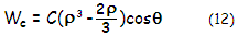
 with
C being the coma peak
aberration coefficient, ρ
the pupil radius normalized to 1 and θ
the pupil angle. Note that
Wc
at its maximum
represents 1/2 of the P-V wavefront error, since it gives identical
value of opposite sign for negative ρ
(i.e. for the opposite half of pupil radius). As shown at left, the aberration peaks for ρ=1
and θ=0° and 180° - i.e. along the axis of aberration - with the sign of aberration changing symmetrically on
both sides of the wavefront (except for θ=0, when deviation is zero
across the pupil radius). Second factor in the brackets - effectively
correction for wavefront tilt - makes the P-V coma error at the best focus
("balanced" coma, shown at left) three times smaller at its maximum than the P-V error at
the paraxial
(Gaussian) focus. The latter is referred to as "classical", or Seidel coma,
where the P-V wavefront error is given by W=Cρ3cosθ
(FIG.
42, middle). with
C being the coma peak
aberration coefficient, ρ
the pupil radius normalized to 1 and θ
the pupil angle. Note that
Wc
at its maximum
represents 1/2 of the P-V wavefront error, since it gives identical
value of opposite sign for negative ρ
(i.e. for the opposite half of pupil radius). As shown at left, the aberration peaks for ρ=1
and θ=0° and 180° - i.e. along the axis of aberration - with the sign of aberration changing symmetrically on
both sides of the wavefront (except for θ=0, when deviation is zero
across the pupil radius). Second factor in the brackets - effectively
correction for wavefront tilt - makes the P-V coma error at the best focus
("balanced" coma, shown at left) three times smaller at its maximum than the P-V error at
the paraxial
(Gaussian) focus. The latter is referred to as "classical", or Seidel coma,
where the P-V wavefront error is given by W=Cρ3cosθ
(FIG.
42, middle).
The
RMS
wavefront error for coma at the best focus, in terms of the peak aberration
coefficient C is:
ωc =
C/720.5
(16)
In terms of the P-V wavefront error it is ωc=2Wc/√32,
with Wc
being, as given above, the coma peak wavefront error (half of the P-V
error).
On FIG. 39, the peak error on the top radius (edge point)
is positive, being farther to the center of a perfect reference sphere
than its perfect reference point, while the peak error on the bottom radius is negative.
This is so
called "positive" coma, with the top section of the wavefront flattened
with respect to the reference sphere, and the bottom portion more
curved. Its comatic tail is oriented outward, away from field center. Presence of the pupil angle factor
(cosθ) indicates that the
aberration is not rotationally symmetrical. The
peak aberration coefficient is given by:
C = cαd3
(13)
with c being the coma aberration
coefficient (simplified notation for
1w31
from Table 4), α
the field angle (in radians) and d the pupil radius.
For general
optical surface, coma
aberration coefficient is
given by:
c=0.5n2[(1/O)-(1/R)][(1/n'I)-(1/nO)]
where I, O are the image and object distance, and n,
n' are the refractive index of incidence and refraction or
reflection, respectively.
Coma aberration coefficient c for either refractive or
reflective surface, for object at infinity, and aperture stop at the surface is given by:
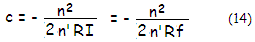
with f being the focal length, and n and n' being the
index of incidence and refraction/reflection, respectively.
For a single thin lens
with the stop at the surface, coma coefficient is:

with p,
q and f being the
lens
position factor,
shape factor and focal
length, respectively.
Thin lens is coma-free if its shape factor
q and position factor p
relate as q=-(2n+1)(n-1)p/(n+1). Lens doublet can have both, coma and spherical aberration cancelled.
For given shape p and q, the sign of coma is
not affected by lens power, i.e. it is the same for positive and
negative lens. However, if placed one after another, their respective
p values - and possibly sign as well - will be different, and
so will the coma induced by each element.
With
regard to the aperture stop position, it does affect coma only with
objectives not corrected for spherical aberration. With an aplanatic
(corrected for spherical aberration and coma for infinity) lens system, stop position
doesn't affect neither coma, nor astigmatism and field curvature.
For
mirror surface, the coma coefficient for any object distance is given by:
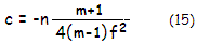
with m being the transverse image magnification (defined
following
Eq. 9.). For distant objects m=0,
n=1 for mirror in air oriented to the left,
and the coefficient reduces to:
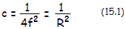
As the aberration function shows,
deviation from the perfect reference wavefront is largest for ρ=1 and
either cosθ = 1 or
cosθ
= -1 (i.e. θ=0
or θ=π
radians, respectively). With θ
being the position angle in the pupil, measured to the plane of the axis of
aberration, the maximum
deviation occurs at the marginal points of the wavefront in the plane of
aberration (FIG.
25,
left). The
deviation is zero for cosθ=0
(i.e. θ=π/2
or θ=3π/2),
which is the wavefront diameter orthogonal to the plane of aberration.
For ρ
smaller than |~0.8|, the deviation changes the sign, as a result
of the two lobe-like deformations, illustrated on FIG. 39, left.
As mentioned,
the above relations for coma aberration are for a mirror with the aperture stop at the surface.
For displaced stop, the coma aberration coefficient c
changes with a factor Δ[
c'=1-(1+K)σ]/σR;,
with Δ being the chief ray height on the mirror (given by a product of the mirror-to-stop separation and incident angle), K being the mirror conic and
σ
the mirror-to-stop separation in units of the mirror radius of
curvature, numerically positive.
Thus, for displaced stop, the aberration coefficient for object at
infinity is:

Since Δ and σ change in proportion to the stop separation, stop position doesn't influence coma of a paraboloid (K=-1),
while cancels coma of any conic K>-1 for the stop separation
σ=1/(1+K).
On the other hand, displaced stop increases coma for K<-1 (hyperboloid).
This applies for objects at infinity; for
close objects for which the mirror object-image magnification m
significantly differs from zero, the change factor in the coma coefficient caused
by the aperture stop displacement is obtained by replacing both unit figures
in the "infinity" object distance factor
c' with (m+1)/(m-1),
or (1-Ω), Ω
being the reciprocal of the object distance in units of the radius of
curvature, numerically positive. It gives the coefficient as:

Note that (1-Ω)
is just a different form of (1-2ψ) parameter, used in
Eq. 9.1, ψ being the reciprocal of the object distance
O
in units of the focal length, ψ=f/O.
The wavefront error changes
with the coefficient. Considering that the magnification m is
negative, coma diminishes with object distance, dropping to zero for
m=-1 (for object at the mirror center of curvature) and stop at the
surface (σ=0), regardless of the
conic. Due to the peak
wavefront deviations with coma affecting relatively small area, the
error averaged over the entire wavefront is smaller for coma than for
spherical aberration for any given P-V wavefront error (FIG. 41).

FIGURE 41: Coma ray aberration as a ray spot (bottom) and the actual
diffraction pattern (top). Top: from left to right, perfect
diffraction pattern of a relatively bright star, diffraction pattern
affected with
0.42 wave P-V wavefront error of coma (corresponding to 0.074 wave RMS, for 0.80
Strehl, thus comparable to 1/4 wave P-V of primary spherical
aberration), and diffraction pattern affected by 0.84 wave P-V
wavefront error of coma (~0.15 wave wavefront error RMS, comparable
to 1/2 wave P-V of spherical aberration). As the
error increases, best focus location shifts from the middle of the
Airy disc in the direction of intensity shift. Unlike spherical
aberration, there is no gain from axial defocus, which is pretty
much obvious from the shape of wavefront deformation. Bottom:
corresponding ray spot plots for identical amounts of the aberration. The "V" shaped
form obvious in the ray spot doesn't become apparent in the actual
diffraction pattern until the error exceeds ~1 wave P-V, provided
there is sufficient magnification to make it visible to the eye.
For small levels of the aberration,
the shift from the Gaussian image
point to the best, i.e. minimum RMS focus location is transverse, in the image plane and along
the axis of aberration, given by 4FC/3=8FWc/9. That places best focus at
1/4.5 of the blur length away from the Gaussian image point (the tip).
It corresponds to 2/3 of the separation between Gaussian focus and
centroid, the latter being the same for the geometric image and PSF.
The shift effectively
corrects for the wavefront tilt element. Unlike spherical aberration,
the peak aberration coefficient C for coma does not equal the p-v
wavefront error. At the location of best focus, the P-V wavefront error
is 2C/3, with the peak wavefront error being
±C/3.
The error is smaller by a factor of 3 than at the location of Gaussian
image point, for which the tilt is not corrected.
 As with other aberrations,
focus with the lowest RMS wavefront error produces the highest PSF peak only as
long as the magnitude of aberration remains relatively small. In general,
under 0.15 wave RMS. Specifically for coma, the PSF peak shifts away
from the best focus (with respect to the magnitude of wavefront error),
as defined above, as the aberration exceeds 0.76 wave P-V (0.134 wave
RMS). For larger errors, the PSF peak shifts somewhat back, generally closer to the
Gaussian focus, but its exact location varies with the error magnitude
(left).
As with other aberrations,
focus with the lowest RMS wavefront error produces the highest PSF peak only as
long as the magnitude of aberration remains relatively small. In general,
under 0.15 wave RMS. Specifically for coma, the PSF peak shifts away
from the best focus (with respect to the magnitude of wavefront error),
as defined above, as the aberration exceeds 0.76 wave P-V (0.134 wave
RMS). For larger errors, the PSF peak shifts somewhat back, generally closer to the
Gaussian focus, but its exact location varies with the error magnitude
(left).
Simulations of the actual PSF at right show the shift
in 2-D. It occurs along the axis of aberration (or, in terms of the
geometric ray spot, along its axis of symmetry), hence the magnitude of
shift diminishes from its maximum for line of sight perpendicular to the
axis, to zero for line of sight coinciding with the axis of aberration.
Image below shows main characteristics of coma aberration on the
ray spot plot and the corresponding PSF - as a X/Y plot and
diffraction image - for a 200mm f/5 paraboloid with stop at the
mirror's focus (to eliminate astigmatism) and on the best field
surface (R=-1m).

The raytrace (OSLO Edu) choses as the center point (0,0) the best
focus, i.e. center of a reference sphere having the lowest RMS error
with respect to the actual wavefront. Peak intensity, however, is
shifted along the axis of aberration (Y axis), closer to the Gaussian (geometric)
focus. At this magnitude of aberration, neither the central intensity,
determining the Strehl ratio,
defined as a ratio of aberrated vs. unaberrated central PSF
intensity (in this case about 0.05), nor the intensity corresponding
to the minimum RMS focus,
coincide with the PSF peak intensity.
Coma
transverse
aberration also can be expressed in terms of the peak aberration
coefficient C. Tangential coma is given by T=6fC/n'D,
f
being the focal length and D the aperture diameter. For mirror
oriented to the left, n'=-1, and T=6FC, with F being the focal ratio number,
F=f/D. With the peak aberration coma
coefficient C=αD/32F2
for distant objects, tangential coma can be expressed directly as:
 as transverse aberration
(h=αf,
the linear height in the image plane), and
Ta
= T/f = 3h/16fF2
= 3h/16DF3
= 3α/16F2
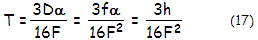
(17.1)
as angular tangential coma (in radians). In terms of the peak coma wavefront
error Wc,
T=18FWc
(with the peak wavefront error being, as mentioned, 1/2 of the P-V
error). In terms of Airy disc diameter, tangential coma is given by 18Wc/2.44, with Wc
expressed in units of the wavelength used to calculate the Airy disc.
For Wc=0.21, the 0.80 Strehl level, that gives tangential coma
of 1.55 Airy disc diameters.
From Eq. 11, tangential
coma changes in proportion to the square of the pupil (zonal) height, or
with
ρ2
for the pupil radius normalized to
1. As already mentioned, sagittal coma S=T/3;
it is larger than the P-V wavefront error by a factor of 3F.
Geometric coma blur (tangential coma) can also be expressed in terms of the RMS
wavefront error ω,
as t=ω√2592/2.44,
in Airy disc diameters; also, in terms of the peak aberration coefficient
as t=6C/2.44 (in Airy disc diameters), for the RMS wavefront error
ω
and peak aberration coefficient C in units
of the wavelength. For any given RMS
wavefront error, tangential coma is smaller than spherical aberration
blur at the best focus by a factor (81/360)1/2.
Finally, the
RMS ray spot radius for balanced coma
is given by rRMS=2√7/9FC,
which in terms of the tangential coma becomes √7/9T/3.
In other words, it is smaller than the tangential coma blur by a factor
0.294. The coma RMS blur radius is smallest when measured around coma's PSF
centroid (at 1/3
of the tangential coma, along the axis of aberration; C on
Fig. 39 left). The smallest RMS blur radius is given by r'RMS=√8/3FC,
or smaller by a factor of 0.926 than the RMS blur radius centered at the
diffraction focus. However, due to the increase in wavefront tilt error
component, the P-V error of coma for the wavefront centered at the PSF
centroid is at the minimum for
ρ=1/√3,
and for the aberration function Wc= C(ρ3-ρ)cosθ.
This gives the peak wavefront error Wc=-0.3849C,
greater by a factor of 1.15 than the peak wavefront error - and RMS
wavefront error - at the best focus.
In units of Airy disc diameter, the RMS
blur diameter at the best focus is RRMS=2√7/9C/1.22,
with the peak aberration coefficient C in units of the
wavelength. Since the P-V wavefront error of coma W=2Wc=2C/3,
it can also be written as RRMSW√7/1.22.
In terms of coma RMS wavefront error
ωc,
it is RRMS=4√14ωc/1.22.
EXAMPLE: For a 200mm f/5 paraboloid,
thus d=100 and R=-2000, the peak wavefront error of coma at 1.4mm
off-axis (with the field angle α=1.4/1000=0.0014),
setting ρ=1
and θ=0
in Eq. 12, comes to C/3. With the peak aberration coefficient C=cαd3=αd3/R2=0.00035mm,
the peak wavefront error of coma is
Wc=0.0001167mm.
The P-V wavefront error is
twice as much, or 0.000233mm. In units of 550nm (0.00055mm) wavelength, it is 0.424 (1/2.36 wave). The
RMS wavefront
error is ω=C/√72=0.000041mm
or, in units of 550nm wavelength, 0.075 (1/13.33 wave). The RMS
wavefront error can also be obtained from the P-V wavefront error as
ω=2Wc
/√32.
Either way, the aberration is at the conventional
"diffraction-limited" level.
The transverse tangential coma
T=6FC=0.0105mm, or 1.56 Airy
disc diameters. Therefore, angular tangential coma
Ta=T/f is 0.0000105 in radians, or
206.265x0.0000105=2.17 arc seconds. Since both, wavefront error and geometric (ray)
aberrations are directly proportional to the aberration coefficient,
it implies that they are in a constant proportion themselves. In
other words, doubling the wavefront error also doubles the geometric
aberration. The RMS blur
radius
rRMS=2√7/9FC=0.000617mm,
and the RMS blur diameter in units of the Airy disc diameter
RRMS=2√7/9C/1.22=0.92,
for C in units of the wavelength.
Analogous to the higher-order spherical aberration, strongly curved surfaces generate
higher-order (secondary) coma, similar in appearance to
its lower-order form, but not identical.
Unlike primary coma, where the zonal ray circles increase with the
square of zonal height, and the circle center is at its diameter away
from Gaussian focus, with secondary coma the zonal ray circle diameter
increases with the fourth power of zonal height, while its center shifts
by 1.5 the circle radius from Gaussian focus. As a consequence, the cone
formed by these circles is wider, outlining a 90°
angle (FIG. 42). The ray geometry indicates that secondary coma displaces
relatively less energy into the outer portion of the blur, with the
sagittal coma being only 1/4 of the tangential coma (blur length).
Accordingly, the resulting diffraction image would have less noticeable comatic tail, and shorter, more compact sagittal image than primary
coma.
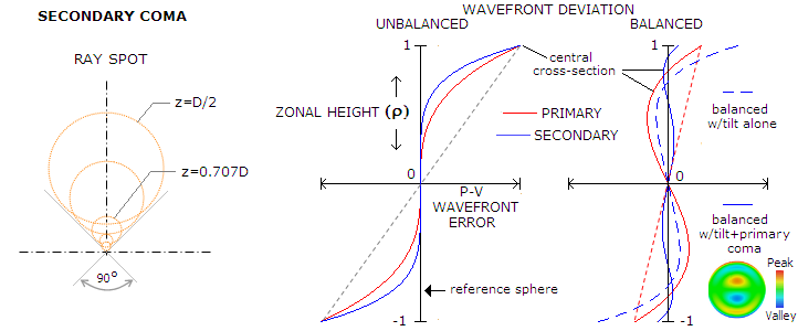
FIGURE 42: Ray spot for secondary coma is
wider than that for primary coma, with the length-to-width ratio 1.25
vs. 1.5 (left; z stands for zonal height). However, since its
deviation increases at a faster rate (5th vs. 3rd power of zonal
height), its unbalanced form has smaller overall deviation for given P-V
wavefront error, with the RMS wavefront error smaller by a factor of
0.78 (middle). Also, since it can be balanced not only with tilt, like
primary coma, but also with primary coma as well, its balanced form has
the P-V and RMS wavefront error reduced by a factor of 0.1 and 0.21,
respectively. Below are 3D plots of balanced primary and secondary coma.

According to Wcs=Csρ5cosθ
(subscript s for "secondary"), for given value of the peak
aberration coefficient, the P-V wavefront of secondary coma at the
Gaussian focus is identical to the P-V wavefront error of primary coma, but the RMS wavefront error is
smaller by a factor of 0.78. When balanced with wavefront tilt, the P-V
error Wcst=Cs(ρ5-0.5ρ)cosθ
is reduced by a factor of 0.5. But it is further reduced by balancing it
with primary coma, to Wcstp=Cs(ρ5-1.2ρ3+0.3ρ)cosθ,
for ρ=1 (both reversal points, at ρ=0.31 and ρ=0.79 radius, have smaller
deviation), or 1/10 of its magnitude at the Gaussian focus.
In ray tracing, balancing secondary coma, if
significant, is a part of optimization. After cancelling lower-order coma in the 3rd
order (for transverse ray, 4th order on the wavefront) approximation, residual higher-order
(5th transverse, 6th on the wavefront, or secondary) coma is minimized by
reintroducing lower-order coma of opposite sign, with the coefficient
(absolute value) larger by a factor of
1.2 (plus tilt factor, which determines lateral shift from Gaussian
focus, i.e. point at which the wavefront error is minimized). As mentioned, the combined RMS wavefront error is smaller by a factor of 0.21
than for unbalanced secondary coma. This means that, similarly to
the secondary spherical aberration, secondary coma cannot be entirely
removed by balancing it with the lower-order form, only minimized.
However, since the magnitude of unbalanced secondary coma is typically
relatively low, and both, primary and secondary coma have the same rate
of increase (in proportion with field angle), the level of balanced coma
is usually negligible.
◄
4.1.3. Higher-order
spherical aberration
▐ 4.3.
Astigmatism
►
Home
| Comments |