|
telescopeѲptics.net
▪
▪
▪
▪
▪▪▪▪
▪
▪
▪
▪
▪
▪
▪
▪
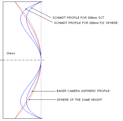
▪ CONTENTS ◄ 10.2.2.1. Schmidt camera: aberrations ▐ 10.2.2.3. Schmidt telescopes ► 10.2.2.2. Wright and Baker cameras; HyperstarThe similarity between these two camera concepts is that they both use Schmidt corrector with aspherized mirror, although the form of mirror aspherizing is exactly the opposite. In addition, the Baker camera uses sub-aperture corrector as an integral system element. WRIGHT CAMERAIn 1935, just a few years after the introduction of the Schmidt camera, Franklin Wright (Berkley, California) presented his "short" alternative to the original arrangement. He placed Schmidt corrector at the focal plane (FIG. 171A), and aspherized the mirror in order to cancel coma resulting from the altered stop position. While astigmatism remains present in the Wright camera, it conveniently combines with the mirror Petzval curvature to result in a flat best image surface. The Wright design logic can be followed with two simple relations. Knowing that mirror coma changes with a factor 1-(1+K)σ, where K is the mirror conic and σ the mirror-to-stop separation in units of the mirror radius of curvature, and that mirror's best astigmatic surface becomes flat with the stop separation σ=[1-√0.5(1-K)]/(1+K), zero coma requires σ=1/(1+K), which in turn, for the flat-field stop location requires √0.5(1-K)=0. Thus, to a third-order, for zero coma and flat astigmatic field K=1 (oblate ellipsoid) and σ=0.5. Reducing the conic K at this stop location would introduce both, coma and field curvature (the conic is a subject to minor changes in optimizing for the effect of higher-order off-axis aberrations, mainly coma).
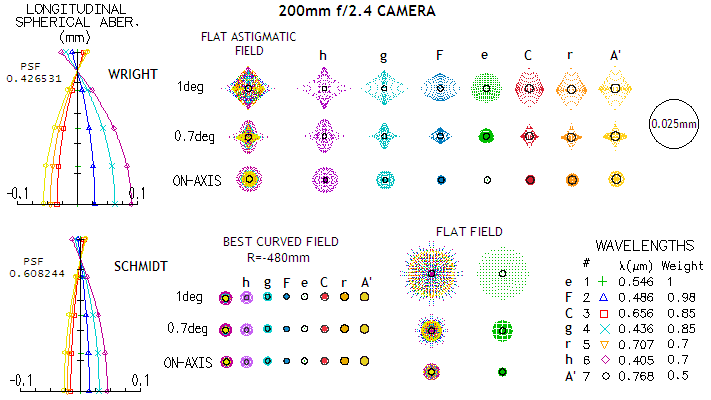
With mirror astigmatism changing in proportion to Kσ2+(1-σ)2, for the given values of K and σ, Wright camera astigmatism is 1/2 of the mirror astigmatism with the stop at the surface. That gives the P-V wavefront error (from Eq. 19-20) as W=(αD)2/8R = -Dα2/16F = -h2/16DF3, and the transverse error - as the diameter of the least circle of confusion - T=4FW=-h2/4DF2, where α is the field angle in radians, D the aperture diameter, R the mirror radius of curvature, h the linear height in the image plane and F the mirror focal ratio (the minus sign for transverse aberration indicates that the aberrated ray in tangential plane focuses shorter than perfect reference wavefront). Glance at the properties of the corrector shows that needed aspheric coefficient b for cancelling spherical aberration of the Wright's primary mirror is doubled in comparison to the original Schmidt arrangement. To a third-order, it is given by b=2(K+1)[1-(Λ/16F2)]/R3, which is identical to Eq. 103, except that the mirror aberration coefficient for spherical mirror (1/R3) is now given in its general form: (K+1)/R3. Simpler relations, given by Rutten and Venrooij (p285) for Schmidt corrector camera system in general, give the corrector power (which is the needed aspheric coefficient b normalized to 1) as P=1/σ, and needed conic for an aplanat as K=(1/σ)-1. Doubled aspheric coefficient - or "power" - with respect to the standard Schmidt results in a doubled wavefront error (Eq. 106) and transverse aberration (Eq. 107.1) of spherochromatism. Considering low spherochromatism of the standard Schmidt, it becomes significant only at ~ƒ/2 and faster systems. The need for more strongly aspherized corrector and, especially, strongly aspherized fast mirror (into a rather unpopular type of aspheric shape) is more of a disadvantage. On the good side, Wright camera is only about half the length of the standard Schmidt. Since the corrector nearly coincides with the image plane, it can support film/detector assembly, clearing the optical path from supporting vanes. Wright's flat-field performance is better than that of a comparable standard Schmidt, although it is a mixed bag, considering its inferior axial correction due to spherochromatism. Its geometric off-axis blur size is smaller by a factor of two (FIG. 171B), with the defocus blur diameter in the Schmidt - from Eq. 26, after substituting the image curve depth for L - being given by Bs= h2/2DF2.
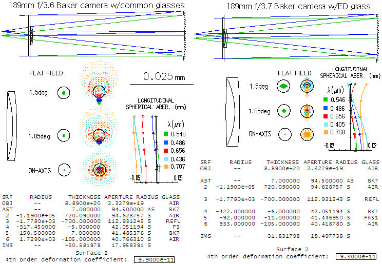
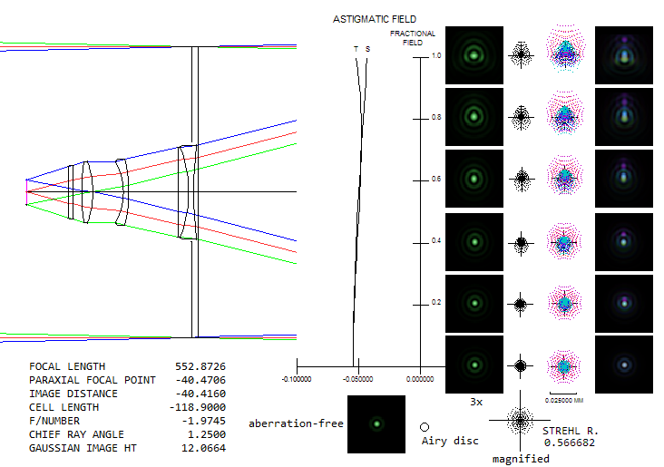
In terms of the wavefront error, the flat-field P-V errors are identical in both, Schmidt and Wright, given by W=-h2/16DF3. However, while the off-axis error in the flat-field Schmidt results from defocus, in the Wright camera it is caused by astigmatism. Since the RMS/P-V error ratio is smaller by a factor of √0.5 for astigmatism, the actual quality flat-field radius in the Wright camera is larger by a factor of 1.4. BAKER PARABOLIC CAMERAAmong many of the designs invented by James Baker is a camera that uses paraboloidal mirror (K=-1) with sub-aperture coma corrector. Since the latter also induces under-correction, Baker placed a Schmidt corrector inside the focus of a paraboloid to offset the aberration. The coma corrector also nearly eliminates image curvature and astigmatism generated by the mirror, producing flat, highly corrected field. Originally, the camera was intended for imaging in a limited spectral range (as plots below indicate, green and blue, with the red and violet left out), but it can be modified to have near-perfect correction across the entire visual range, and somewhat into infrared.
The coma corrector also reduces mirror focal length by over 20%, making mirror fabrication relatively easy for camera focal ratios down to ~ƒ/3. The Schmidt corrector, however, is not as weak as its 4th order aspheric parameter might suggests. Using Eq. 102 we find that the focus factor Λ corresponding to the parameter and radius value is 5.06. And Eq. 101 gives the maximum depth (for ρ=1) of nearly 0.03mm, which agrees with ray trace (field lens induces 5-6% more spherical aberration than what the mirror would have, if spherical, hence the corrector is that much stronger than what it would have been for spherical mirror). Since the factor Λ is larger than 2, it implies that the neutral zone is out of the surface, i.e. that the profile is a smooth convex aspheric. What creates this profile depth is the radius value, which is disproportionally strong for the aspheric parameter. Its purpose is not correcting spherical aberration - that is determined by the parameter value alone - rather to minimize spherochromatism by determining longitudinal placement of non-optimized wavelengths. In this particular arrangement, with very low spherochromatism due to the low aspheric parameter (i.e. relatively low amount of the aberration to correct), the primary role of putting the radius on the aspheric is to minimize lateral color error (change in the radius value affects the longitudinal chromatic foci, but not the lateral color error, since the corrector is at the aperture stop and its central portion is practically a plano parallel plate for this weakly curved surfaces). Without it, the needed corrector depth with the 0.707 neutral zone profile would have been less than 2 microns. Some other glass combinations may allow for the weaker, shallower profile - for instance, FPL53/FK5 has a good control of lateral color with the radius value of -155,000mm, resulting in 26% smaller depth. HYPERSTARStarizona's Hyperstar is a camera system created for the standard Celestron SCT telescopes. It works by taking the secondary out and placing a 3-group 4-element corrector in front of the primary's focus. Below is the C11 version, according to Smith/Ceragioli/Berry's "Telescopes, Eyepieces, Astrographs", which state that the data is taken from the patent documentation (#7,595,942 from 2009) and WIPO database (WO2008109563), with the latter actually furnishing complete data. It is similar to the Wynne corrector in configuration. The 11-inch SCT similar to the Celestron's system (top) is shown first, and the Hyperstar system used on it after that. The ray spot plots for the Hyperstar are given for the plane of the best axial focus (bottom left), field edge (middle) and 0.7 field zone (right), with the second one being the closest to those in the book (focus not specified). Also, in the book they are given for the SCT system with a 0.866 neutral zone Schmidt corrector, which includes 6th order aspheric deformation. There is no corrector configuration specified in the patent documentation, but it is more likely that the actual Celestron's units use 0.707 neutral zone correctors, which are both, easier to make and have less than half of the spherochromatism (measured as wavefront error) of the 0.866 neutral zone corrector. Hence, the SCT here uses 0.707 neutral zone corrector. 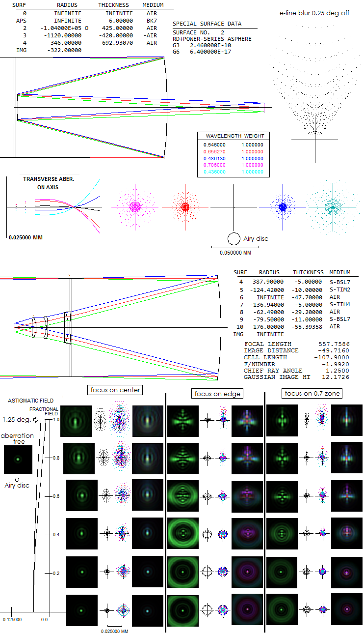
Central obstruction of the SCT is 34%. The SCT field radius given is 0.25°, or little over 12mm. At f/2, which is the effective focal ratio of the Hyperstar system, this linear radius corresponds to 1.25° angular field radius. Prescription for the Hyperstar is given separately, knowing that the vertex of its front surface coincides with the front surface of the Schmidt corrector. This, obviously, makes important to know the exact specifications of the Celestron's SCT, which is not the case here, but it comes close enough to show the level of correction achievable with the Hyperstar. Spherical aberration at the field center is about 0.1 wave RMS, 0.68 Strehl at the best focus. As the astigmatism plot at left shows, the field is not quite flat, with the defocus between the best axial and edge focus of about 1.9 wave P-V. Longitudinal astigmatism of 0.018mm at the edge (given as separation between the tangential and sagital surface , the latter here being at left) indicates 0.018/8F2=0.00056mm, or 1 wave P-V (this is the level of astigmatism when its diffraction image has the most pronounced cross-like pattern). Note that the 0.025mm scale is for the ray spot plots, with the diffraction images shown about 2.5 times larger than the size corresponding to the spots (for making the Airy disc visible).
Looking at the ray spot plots, the best overall focus seems to be
on the 0.7 zone; however, diffraction images favor focus on the
best axial focus. Overall, the system, if well aligned, should perform well
whenever is the requirement of having ray spot plots for this
spectral range within 10 micron square,
although diffraction images show that the spot size alone is not
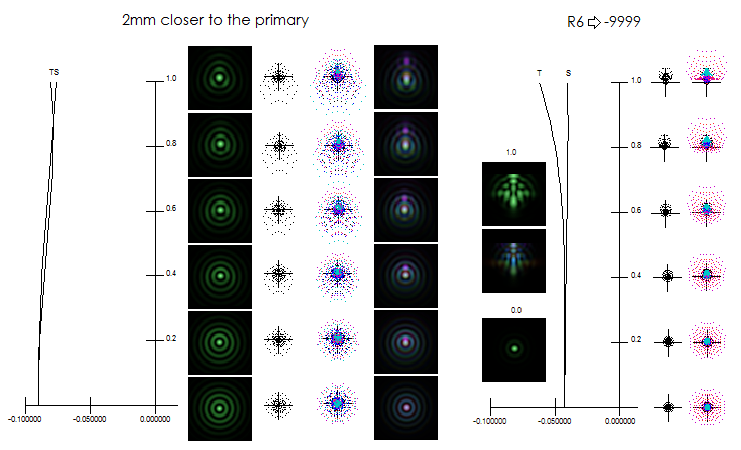
a reliable criterion. Interestingly, if the lens system is placed
2mm closer to the primary, the field becomes essentially flat,
with zero astigmatism, and field definition limited only by the
spherical aberration residual (below).
It increases spherical aberration, which is indicated by the
separaton between the origin of astigmatic plot - by default
placed at paraxial focus - and 0 point, representing
best axial focus (here 0.09mm, giving 0.09/64F2=0.00035mm,
or about 0.6 wave P-V). It shows some lateral color,
which is more obvious on diffraction images reduced in size.
Spherical aberration can be reduced by putting a very weak
radius on R6 (right), bringing it back to the privious level.
Some astigmatism is reintroduced, but the overall correction
level is better. It illustrates just a few of possibilities
to optimize this design. It should be noted that some undercorrection
should be a part of design, since any plane-parallel plate
(CCD window, filters) will induce overcorrection; in f/2
beam, at a rate of nearly 1/10 wave P-V per mm of thickness.
The negative longitudinal aberration (paraxial to best axial focus)
indicates undercorrection, implying that the configuration at
left is near optimal (proprietary papers does contain reference
to about 5mm thick "flat glass"). It is probably that the corrector-to-primary
separation is about 2mm smaller in the actual C11 unit than in the
above model. This brings us to what should be the closest to the
actual Hyperstar. Taking configuration at left with 5mm of "flat glass"
added gives output shown below.
Edge astigmatism is about 1/2 wave P-V, with the dominant aberration
across the field being primary spherical, at about 1/3 wave P-V.
Axial color error is worse in the red - 0.9 and 1.5 wave C
and r line, respectively - than in the blue/violet (0.5 and
0.6 wave P-V F and g line, in that order). Lateral
color error is also the largest in the red, with about 0.006mm separation
vs. green at field edge. Overall, correction errors are quite small,
and could be further reduced. This is in line with the
statement in the proprietary papers that the systems
specified (for 8, 11 and 14-inch SCT) are just illustrations
of a number of possible variations of this corrector; those
given there may not be the best they can be - that was probably
reserved for the actual units.
The configurations for
C8 and C14 SCT are different from this one, and one from another,
but they probably have a similar level of correction.
It is to expect that the blur size nearly scales with the
aperture, although the field size - angularly larger in the
smaller aperture for given linear field - is also a factor.
|
 FIGURE 171A: Schmidt and Wright camera of identical apertures and focal ratio. Wright camera is only 1/2 the length of the Schmidt. However, from practical standpoint, with twice as strong corrector as required for the Wright, the Schmidt would have relative aperture greater by a factor of ~1.25 and the tube longer by a factor of 1.6, not 2. And factoring in substantial amount of work needed to make Wright's strongly aspherized primary, even faster and shorter Schmidt could be made with similar amount of time and effort invested. The tube length difference between the two would become relatively small; the only advantage of the Wright camera would be its flat-field performance, and the absence of spider vanes. On the other hand, Schmidt camera would have far superior best field performance, less chromatism and significantly larger relative aperture. Considering that field curvature in the Schmidt can be easily corrected with a field flattener lens, Wright camera has quite limited appeal.