|
telescopeѲptics.net ▪ ▪ ▪ ▪ ▪▪▪▪ ▪ ▪ ▪ ▪ ▪ ▪ ▪ ▪ ▪ CONTENTS ◄ 11. MISCELLANEOUS OPTICS ▐ 12.2. Eyepiece aberrations I ► 12. TELESCOPE EYEPIECE12.1. Eyepiece functions and properties
•Focal length
•Field of view
•Exit pupil size
•Eye relief
•Light transmission
The image formed by the telescope objective is real, and can be observed
directly. However, as explained in Telescope eyepiece is a complex positive lens system placed between the eye and the image formed by the objective. If the object image formed by the objective is located at the ocular's front focal plane, the eyepiece images every image point at infinity - in other words, it transforms (desirably) spherical wavefronts emerging from the object image's points into flat wavefronts merging at the location of the eyepiece exit pupil (in terms of rays, the eyepiece turns diverging cones emerging from the objective's image into collimated pencils of light, FIG. 209). These wavefronts enter the eye, which transforms them into near-spherical and have them focus onto the retina, creating the final magnified apparent image.
The figure illustrates basic properties
of a telescope eyepiece: focal length, field of view
(directly determined by its field stop size), exit pupil
and eye relief. Assuming perfect eyepiece and eye, image space of the image formed by them will be identical in size and shape to the image in the objective's image space. Below is raytrace of a 200mm f/5 mirror alone, and with eyepiece, one of 17mm focal length - identical to the optical focal length of the human eye - and one with twice longer focal length. For both, eyepiece and eye is used OSLO "perfect lens". The only aberrations are those of the mirror, less than 0.02mm longitudinal astigmatism at 0.25° field radius with the best field curvature radius identical to the focal length, only of opposite sign.
Longitudinal astigmatism in the eye image is a bit smaller than for mirror alone, probably due to beam manipulation by perfect lens (in order to keep image aberration-free, perfect lens has to widen oblique pencils in the vertical plane in order to: 1 - cancel astigmatism, and 2 - compensate for the longer path of oblique pencil to a flat image plane; hence, pencils are wider by a 1/cos2α factor, α being the pencil-to-axis angle). Image height on the retina remains unchanged with 34mm eyepiece, despite the twice larger image by the objective (assumed is unchanged eyepiece AFOV, hence twice larger field angle in the image by the objective), because the twice larger exit pupil makes the eye twice faster a system, with the image scale cut in half. In the real world, both eye and eyepiece contribute their own aberrations, which affects the final astigmatism and field curvature, but the overall image scale remains unchanged. 1. FOCAL LENGTH The main eyepiece parameter, determining its basic function - magnification - is its focal length ƒe. Normally, it cannot be directly measured as the separation between the lens and image of a distant object, because the lens (i.e. eyepiece) thickness is large compared to the f.l., and the effective entrance pupil is projected into the eyepiece. From Pex=ƒe/F it follows that ƒe=FPex, i.e. eyepiece focal length is given by a product of the telescope focal ratio and exit pupil diameter. That, of course, requires knowledge of telescope's focal length a precise measurement of the eyepiece exit pupil. An alternative method of establishing ƒe is measuring the image size of a relatively distant object vs. size of its image produced by the eyepiece. From the geometry of image formation (FIG. 7), the proportion between object and image height ho and hi, respectively, equals that between object and image lens separation, So and Si, in the same order, thus Si = Sohi/ho, irrespectively of lens thickness. With focal length defined by Eq. 1.4 as ƒ=SiSo/(Si+So), and hi/ho=Si/So, the relation between image separation and focal length is Si/ƒ=(Si+So)/So=(Si/So)+1=1+(hi/ho) and ƒ = Si/[1+(hi/ho)] = So/[1+(ho/hi)] Thus eyepiece focal length can be obtained from the measurements of the object size (ho), image size (hi) and object distance (So). The object's image can be measured either as projected on a piece of paper, or directly as seen at the eye lens. Best object type is a bright, uniform surface with well defined boundaries, such as a well lit window. Size of the image should be kept at the minimum allowing accurate measurement, in order to minimize distortion (which tends to enlarge outer field portion, thus to result in shorter than actual eyepiece focal length if that portion of the field is used). Also, greater object distance - 50 to 100 focal lengths - will minimize the error of (most likely) adding to the object distance, measured from the field lens, a small differential between that point and second principal plane of the eyepiece. 2. FIELD OF VIEW The next important eyepiece parameter is its field of view. Limit to the eyepiece apparent field is set by its field stop, an axially centered opening in front of the field lens, which for focused eyepiece coincides with the objective's image plane. Angular size of the field stop as seen from the center of the entrance pupil (α, FIG. 209) is called true field of view (TFOV), and its angular size as seen through the eyepiece (ε, FIG. 209) is apparent field of view (AFOV) of a telescope (here, both are presented as field radius; often times, the terms are also used for the field diameter).
The AFOV/TFOV ratio approximates telescope magnification; however, its approximate accuracy varies with the degree of eyepiece image distortion. Since magnification is defined as apparent image size vs. apparent object size, it is given by the ratio of tangents, or M=tan(AFOV/2)/tan(TFOV/2). With the TFOV being always a small angle, image distortion is negligible, and the actual image angle is practically given by tan(TFOV/2)=T/2ƒ, T being the diameter of eyepiece field stop (being a small angle, it is also closely approximated in degrees by TFOV~180T/2ƒπ).
The field stop diameter corresponding to the actual (distortionless) angular field is always smaller than the stop implied by the nominal eyepiece AFOV. With the usual magnitude of distortion ranging from up to 5% with 40° AFOV to up to 20% with 80°, it is approximated by T~ƒeAFOV/[58-(AFOV/58)], for AFOV in degrees (plot at left).
The distortionless AFOV is directly related to the field angle
of the objective, which is smaller according to telescope magnification
(keep in mind that magnification is not angular, but relates to the
tangens, so the accurate way of relating the two is by determining
the field stop radius from the eyepiece AFOV, divide it with magnification
and then findthe corresponding field angle). Figure below shows the
limit to zero-distortion AFOV imposed by eyepiece barrel, i.e. without
a field stop ring.
3. EXIT PUPIL SIZE
Another important eyepiece-related parameter is the size of
its exit
pupil. It directly determines image brightness level
relative to the object, as well as the level of
eye aberrations. The size of eyepiece exit pupil is inversely
proportional to telescope magnification. For the relative magnification m, in units of aperture diameter, eyepiece exit pupil is given by 1/m for aperture in mm, and by 25.4/m for aperture in inches. So, for instance, relative magnification of 0.5 per millimeter of aperture (50x for D=100mm, with m=0.5), results in 2mm exit pupil diameter, and so does 12.7x per inch of aperture magnification (m=12.7). In terms of the
telescope focal ratio F=ƒobj
/D, exit pupill diameter is given by P=ƒe
/F, where ƒe
is the eyepiece focal length. Another important number related to
the exit pupil diameter is the Airy disc angular diameter, given by
4.6/P(mm) in arc minutes.
At the exit pupil size larger than
about 2mm in diameter, eye aberrations begin to dominate
diffraction effect, increasing progressively with the pupil size.
Thus, telescopic resolution is aberrations-limited for exits pupils
larger than ~2mm, and diffraction-limited
for smaller pupils.
4. EYE RELIEF
Eyepiece eye relief - the
separation between the eye and exit pupil - is mainly
important for observing convenience.
As with most anything else, too little is as undesirable as too much.
Short eye relief, typical of the short f.l. conventional eyepieces,
prevents observer from placing eye at the exit pupil, thus
effectively reducing apparent field. It also causes eye strain,
detrimental to the quality of observing. Too long eye relief, often
encountered with long f.l. eyepieces, especially when used with a
conventional (not telecentric) Barlow lens, makes it difficult to
find exit pupil and keep eye pupil on it. Size of eye relief varies
mainly with the eyepiece type and design (FIG. 215
and FIG. 213),
although it may vary somewhat within them as well.
Image below (under Light transmission shows variation in
eye relief of some familiar eyepiece designs.
5. LIGHT TRANSMISSION
The two factors determining light transmission in the eyepiece
is reflection off its lens surfaces, and in-glass absorption.
Nothing can be done about the latter, which leaves reflection
as the only concern, and not so much with respect to light
transmission itself, but more for the negative effect of
reflected light on image quality.
Aside a few specialty eyepieces employing only a few refractive
surfaces, with either air-glass or glass-glass boundaries, modern
eyepiece designs have anywhere from several to a dozen or more
such surfaces. It makes application of antireflective coatings even
more important than with refracting objectives or subaperture correctors.
More so considering large incident angles at their lens elements,
increasing reflection loses toward lens edge. Four random designs
show that incident angles for the edge cone central ray
go up to 40° with the standard 50-deg
AFOV eyepiece, and up to 50°, or so, with 80-deg AFOV eyepieces
(below). All four are 10mm f.l. units, with the Nagler's positive
lens group having 23mm f.l., indicating the Smyth lens
magnification factor of 2.3. For each surface, given are
the angle between z-axis (optical axis) and ray exiting surface (Yang) and
angle of ray incidence onto surface (Iang), in degrees.
With today's ultrawides edge incident angles can be even larger (with
each surface, the top angle is vs. optical axis, and the
angle below it is vs. normal to the surface). This creates the basis
needed to relate meaningfully to the reflectance vs. incidence graph
(below). It shows
how reflection on the lens surface depends on the incident angle
(uncoated glass, unpolarized light; ni is the
index of incidence, and nt index of transmitting
medium). Plots at right are a magnified area of the plot at left,
showing that reflections off glass-glass surfaces (3, 4) can be significant,
more so considering that they cannot be suppressed with coatings.
The four plots outline reflection range on air-glass and glass-glass
surfaces (form of Fresnel equations - square of a differential -
makes order, air-glass vs. glass-air, and glass1-glass2 vs. glass2-glass1
inconsequential with respect to the reflectance level). The denser
glass, i.e. the higher refractive index, the higher reflectance: for
normal incidence air-glass (or the other way around) reflectance
is 4% for glass refractive index n=1.5 (1), and more than twice as much
for n=1.8 (2).
While reflections off air-glass surfaces (1,2) can be significantly
reduced with antireflective coatings, reflections off glass-glass
surfaces (3,4) remain and can be significant: over 2% at 45°
incidence with n=1.5 and n=1.8 (3). Also, a single layer
antireflective coating, like MgF2, while
For near-normal incidence, reflectivity depends on the
relative strength of refractive index of the coating vs.
subtrate. For 1/4 wave thick layer of MgF2 (refractive
index 1.337 at 546nm), reflectance varies from less than
0.8% with n=1.9 subtrate, to 2.5% with n=1.4 (below, left).
The differnce can be significant, as shown at right for
MgF2 layer on BK7 (1) and N-LASF31 (2). Reflectance can
be further reduced with multi-layer coatings: with only
two layers reflectivity around central wavelength can
be reduced close to zero (3). With three layers a more
uniform reflectivity over wider spectral range (4).
The top and bottom layer are 1/4 wave thick, with 1/2 wave
thick mid layer (based on data from Lens Design by Milton Laikin) Absorption
is about 4% per inch of in-glass path, decreasing toward
field edge, although partly offset by the negative - usually dense -
elements becoming thicker toward the edge. For the four eyepieces
shown above (10mm f.l. units), axial glass thickness is from below
9mm (Plossl, Abbe being a bit thicker, around 10mm), to
16mm (Erfle) and 36mm (Nagler1, only the positive group),
hence with approximately 1.4%, 2.5% and 5.8% absorption loss,
respectively.
As mentioned before, eyepiece light transmission is primarily
important because of the light reflected of air-glass and glass-glass
surfaces. Part of it is making to the retina, negatively affecting
image quality. Internal reflections off eyepiece lens' surfaces can be
dominantly diverging toward the eye, dominantly converging, or a mix of the
two. Converging reflections can create ghost images, but what
is the least desirable - and amounts to a poor design - is when
reflections off different surfaces are of the same kind,
reinforcing each other. That may, of course, be to some extent
dictated by the need to minimize the aberrations, but should be
kept as low as possible.
◄ 11. Solar telescope ▐ 12.2. Eyepiece aberrations I ► |
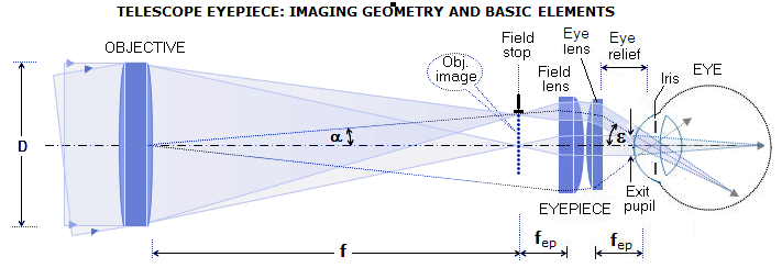
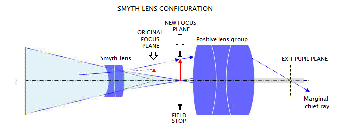

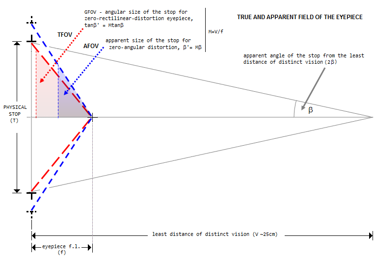 Illustration above shows the geometry of eyepiece's
apparent and true field of view. Since eyepiece effectively
allows the eye to observe objective's image from the distance
equaling eyepiece's focal length, the lenses can be entirely
left out. Eyepiece magnification M is given by a factor of
reduction of observing distance vs. naked eye, equaling V/f
(which multiplied by magnification of the objective, f'/V, f'
being the objective's f.l., gives telescope magnification).
With zero rectilinear distortion, condition of which is that any
zonal height "h" in the field stop becomes M times larger through
the eyepiece, i.e. that the tangent of its magnified angle is M
times larger than tangent of the unmagnified angle. The
corresponding angular size of the field stop in the eyepiece is the
geometric field of view (GFOV). Deviation from this condition
causes curving of straight lines in the eyepiece image.
With zero angular distortion, every zonal angle in the stop is M
times larger in the eyepiece image and, since multiplied angle is
larger than the angle corresponding to its multiplied tangent, the
apparent stop size with zero angular distortion is always larger
than with zero rectilinear distortion, i.e. requires non-zero
(positive) rectilinear distortion. Deviation from zero angular
distortion causes elongation of shapes, either vertical (positive),
or horizontal (negative). Actual apparent stop size can be anywhere
from smaller than GFOV (w/negative rectilinear and angular
distortion) to larger than zero-angular-distortion angular size
(w/positive rectilinear and angular distortion), but usually is
close to the zero-angular-distortion size.
Illustration above shows the geometry of eyepiece's
apparent and true field of view. Since eyepiece effectively
allows the eye to observe objective's image from the distance
equaling eyepiece's focal length, the lenses can be entirely
left out. Eyepiece magnification M is given by a factor of
reduction of observing distance vs. naked eye, equaling V/f
(which multiplied by magnification of the objective, f'/V, f'
being the objective's f.l., gives telescope magnification).
With zero rectilinear distortion, condition of which is that any
zonal height "h" in the field stop becomes M times larger through
the eyepiece, i.e. that the tangent of its magnified angle is M
times larger than tangent of the unmagnified angle. The
corresponding angular size of the field stop in the eyepiece is the
geometric field of view (GFOV). Deviation from this condition
causes curving of straight lines in the eyepiece image.
With zero angular distortion, every zonal angle in the stop is M
times larger in the eyepiece image and, since multiplied angle is
larger than the angle corresponding to its multiplied tangent, the
apparent stop size with zero angular distortion is always larger
than with zero rectilinear distortion, i.e. requires non-zero
(positive) rectilinear distortion. Deviation from zero angular
distortion causes elongation of shapes, either vertical (positive),
or horizontal (negative). Actual apparent stop size can be anywhere
from smaller than GFOV (w/negative rectilinear and angular
distortion) to larger than zero-angular-distortion angular size
(w/positive rectilinear and angular distortion), but usually is
close to the zero-angular-distortion size.
 However, the eyepiece field of view, much larger angularly, suffers
from significant distortion. In the telescope eyepiece, it is
usually positive distortion, which means that image magnification
increases exponentially with the image point height. In effect, the
outer image portion is stretched out and seen at a magnification
higher than that for the inner image portions (this may and may not
be accompanied with
However, the eyepiece field of view, much larger angularly, suffers
from significant distortion. In the telescope eyepiece, it is
usually positive distortion, which means that image magnification
increases exponentially with the image point height. In effect, the
outer image portion is stretched out and seen at a magnification
higher than that for the inner image portions (this may and may not
be accompanied with 


 relatively stable with
respect to the angle of incidence (left), still leaves too much light
bouncing between surfaces, to end up as a stray light on the
retina. More sophisticated, multi-layer coatings,
on the other hand, can reduce reflection to a fraction of
a percent, but are generally more sensitive to the incident
angle increase. Specifics vary with the coating, but large
incident angles may not only cause significant shift in the
optimal wavelength, but also significant - and asymmetrical -
increase in reflectance over certain parts of the spectrum. It
is illustrated by a coating
relatively stable with
respect to the angle of incidence (left), still leaves too much light
bouncing between surfaces, to end up as a stray light on the
retina. More sophisticated, multi-layer coatings,
on the other hand, can reduce reflection to a fraction of
a percent, but are generally more sensitive to the incident
angle increase. Specifics vary with the coating, but large
incident angles may not only cause significant shift in the
optimal wavelength, but also significant - and asymmetrical -
increase in reflectance over certain parts of the spectrum. It
is illustrated by a coating
