|
telescopeѲptics.net ▪ ▪ ▪ ▪ ▪▪▪▪ ▪ ▪ ▪ ▪ ▪ ▪ ▪ ▪ ▪ CONTENTS ◄ 1.1. Point spread function (PSF) ▐ 1.3. Optical system of a telescope ► 1.2. Reflection and refraction
Reflection occurs when a surface exposed to light immediately emits back a portion of the energy received. As the surface atoms absorb wave energy, they become unstable, and regain stability by releasing portion of the absorbed light from their electron orbits. Due to reflection of light occurring in a precisely consistent, predictable manner, reflective surfaces can be manipulated to re-direct or re-shape optical wavefront into spherical, needed for the purpose of imaging. This can be illustrated with a linear array of three silver atoms on the mirror surface (FIG. 3 right). With the atoms being separated by ~1 Ångström (one 10-millionth of mm), the array is essentially flat. As the incident wavefront sweeps over the array, the atoms absorb wave energy and emit most of it right back. However, if the array is inclined in regard to the incident wavefront, the surface slope causes phase shift, with each successive atom's emission lagging behind by a fixed phase fraction. This in turn results in the change of orientation of the principal wavefront, so that the angle of reflection is a negative equivalent of the angle of incidence. In other words, the wavefront reflects at the angle of incidence, only at the opposite side of a normal to the surface. Rays from the neighboring atoms are practically parallel, but they will merge and interfere in the focal zone of the mirror. As the mirror slope gradually changes along its surface, so does the slope of reflected wavefront unfolding from the mirror edge toward center. If the mirror surface has appropriate shape, the reflected wavefront will emerge spherical, with the tightest possible concentration of light energy forming around its center of curvature. 
Refraction of light also results from the phase shift of wavefront points, as their velocity changes within media of different optical properties (left). The ratio of velocity change is expressed by refractive index n as 1/n. Value of n spans from 1 for vacuum, to about 1.8-1.9 for the most dense commonly used optical glass types. An average refractive index of the optical crown is n~1.5, reducing the speed of light by a factor ~1/1.5 (speed of light as the speed of wave propagation, of course, doesn't change, but denser glass has more atoms in the way to excite in order to make the transmission take place, and it adds to the transmission time). Refractive index for any given media vary slightly with the wavelength of light, resulting in unequal propagation, i.e. refraction for different wavelengths - the cause of chromatic aberration. An exaggerated section of a lens can be used to illustrate the phenomenon, mathematically described by Snell's low of refraction (FIG. 3 left). The lens surface is practically flat for a very small section, and inclined with respect to the impinging wavefront as determined by a local surface slope angle. As incident wavefront enters the glass, it slows down, while its portions still traveling through the air maintain the higher speed. This generates phase shift resulting in the change of wavefront orientation. With properly designed lens objective, these sections of refracted incident wavefront unfold into a sphere. Of course, for proper refraction, the glass has to be homogeneous, just as any other media through which light travels.
Local variations in glass density would cause local deformations of the wavefront, resulting in wavefront roughness. More detailed illustration of reflection and refraction shows that the reflected wavefront, by immediately observable geometric requirement, has to have reversed symmetry with respect to the incident wavefront, due to the lineup of the points in phase after reflection being preserved only for the incident geometry rotated by 90 degrees around the axis of incidence (note that the reflected wavefront is perpendicular to the incident ray only for the 45 degree angle). In the case of refraction, the incident ray does proceed into the new medium without change in direction (dashed lines with arrows), and it's still in phase with the corresponding points of other incident rays, all lined up along the new wavefront line, but they are not orthogonal to it. Any line orthogonal to them wouldn't have them in phase anymore (phase difference between points 3 and 1' is shown with a dashed black arrow), i.e. there is no wavefront propagation in that (incident) direction. The new wavefront propagation direction is orthogonal to the orientation in which wave points line up in phase (dotted arrow).
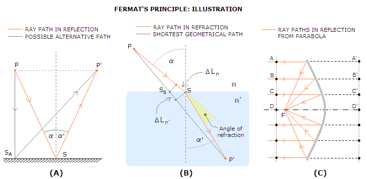
It is easy to show that Snell's law applies to reflection as well. Since for reflection, index of incidence for light traveling from left to right is 1, and index of reflection is -1, substituting these values for n and n' gives law of reflection: n'sinα' = nsinα (law of refraction), for n=1, n'=-1 becomes law of reflection, sinα' = -sinα Both, law of reflection and law of refraction can be derived from Fermat's principle. Some 2,000 years ago, Hero from Alexandria stated that reflected ray of light traverses the shortest possible path between two points (P and P') via reflective surface (FIG. 4A).
Hero's law, however, does not apply to refraction (FIG. 4B). Here, the ray path is geometrically longer than the shortest path via surface - which is a straight line connecting the two points - but light moves from point P to P' in the least amount of time via surface point S. This, of course, apply to reflection as well, and represents the basis of the general principle defined by Fermat, which states that light ray traversing two given points follows the path that requires the least amount of time, i.e. one of the shortest optical path length (shown is ray refracted at air/glass surface, with the refractive index n'~1.5; path differential in air ΔLn is geometrically somewhat larger than that in glass, ΔLn', but less than 50%, which is how much more time light needs in the glass vs. air to span any given distance). Depending on optical surface, there can be more than a single path satisfying Fermat's principle. A ray traversing the two foci via reflective ellipsoidal surface will have an indefinite number of alternative paths requiring the same minimum amount of time - we could say that these rays have no other choice. When the second focus is at infinity, optical path length from any point on the incident wavefront (A, B, C, D...) to the focus point F is constant at the minimum stationary value. For such surface, there is a straight line whose point (A', B', C', D'...) to surface separation equals the corresponding separation from surface to a fixed point (F) - the definition of a parabola (FIG. 4C).
|