|
telescopeѲptics.net ▪ ▪ ▪ ▪ ▪▪▪▪ ▪ ▪ ▪ ▪ ▪ ▪ ▪ ▪ ▪ CONTENTS
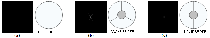
7.2. Spider vanes diffractionPAGE HIGHLIGHTS More often than not, central obstruction by a smaller secondary mirror is accompanied with aperture obstruction caused by its support structure - so called spider vanes. Their effect is generally small, but it can be significant. That makes them worth of a closer look. Unless the secondary mirror cell is supported by an optical window, the supporting vanes - so called spider vanes - are in the optical path, altering emitting area of the wavefront and, thus, creating diffraction effect. As long as the pupil area obstructed by the vanes remains relatively small, spider diffraction is more of a cosmetic damage than seriously affecting contrast level (FIG. 108). Analogously to the central obstruction effect, change in the
normalized central diffraction intensity caused by spider diffraction is, in effect, the ratio of the clear (annular) pupil area with and without the vanes, squared, or
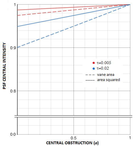
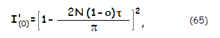
with N being the vane count, τ the relative vane thickness and ο the relative size of central obstruction, both in units of the aperture diameter. The negative factor equals the relative spider area in units of the clear aperture (i.e. annulus) area; this is consistent with the degradation factor caused by central obstruction (Eq. 60). Average spider area is somewhere between 1% and 2% of the clear aperture area. That puts the average spider vane central intensity degradation factor between 0.98 and 0.96. As plots at left show, it decreases linearly with the increase in obstruction (quadratic plots are near flat sections of very wide parabolas). Analogously to the effect of central obstruction, vane obstruction reduces central intensity of the main pattern by a (1-a)2 factor, a being the relative vane area in units of the clear aperture area (for spider vanes, it is the area of annulus), by lowering constructive interference within central maxima and intensifying it in the outer potion of the pattern. For small values of a, typical for spider vanes, the this degradation factor can be written as I(0)'~(1-2a).
The relative intensity distribution is, again as with the CO
effect, based on the peak intensity w/o obscuration effect,
normalized to 1. Energy distribution between the central maxima
and the rings depends, in addition, on the volume corresponding
to the central maxima, relative to the volume of the rings area.
In the absence of exact calculations, best reference point is the
effect of CO with comparable relative obscuration. Taking the same
3-inch aperture, 17% obscuration area corresponds to 41% linear
CO. Graph below summarizes the effects of cross-like and circular
obscuration alone, for 17% areal obscuration. The corresponding
PSFs show that the 1st bright ring is Factor that complicates such comparison are the differences in the size of central maxima. As the magnified inset top left shows, average central maxima reduction due to the cross-like obscuration is less than half of that due to the CO. So are the related effects of increased contrast on the left side of MTF graph and higher cutoff frequency. For small relative obscurations, such are those by the typical 4-vane spiders, these high-frequency gains can be safely neglected, more so considering that the spider effect considered here includes its non-existent central portion behind the CO. The effect is limited to the contrast drop in mid and low frequencies, as shown on the bottom right. With 17% relative obscuration, contrast drop at the 0.2 frequency is 12%; a thin-vane spider obscuring 1% of the area would have little over 0.5% contrast drop there, as little as 0.995 Strehl of aberration averaged evenly over all frequencies. It should be emphasized that this theoretical approach is strictly valid only in the context of near monochromatic point source - i.e. coherent light. In the real world, light processed by the telescopes is typically polychromatic, i.e. partly incoherent, in which case the effect of light obstructions on intensity distribution within diffraction image is significantly smaller. As in the section about the effect of central obstruction, the text continues with the standard coherent light context, but keeping in mind that it is not directly applicable to the field conditions. Depending on the object of observation, the actual spider effect can be much smaller, due to the energy being thrown so far from the Airy disc. For instance, a spider wane D/100 thick will have its principal spike length superimposed over diffraction pattern nearly 100 Airy disc diameters long (only a portion of it visible at best, depending on its telescopic brightness). For a 10" aperture, that is nearly 1 arc minute from the disc center. That would place most of the spike energy out of a relatively small object, not influencing its contrast. For Jupiter, roughly 2/3 of the principal spike fall outside the planet's disc, with 1/3, or so, of the spikes' energy left in, lowering the contrast. Assuming 4-vane spider and 25% obstruction, it would cause little over 1% actual average contrast loss (nearly 0.99 Strehl equivalent), not 4% as indicated by Eq. 65. On the other hand, on large objects like the Moon, nearly entire spikes' energy remains within the image, and the effective contrast degradation factor is ~0.96. There are various vane configurations possible, but the only result is a different form of energy distribution - the amount of energy transferred out of the Airy disc remains unchanged for any given vanes area. Given size of central obstruction, the vane area is directly proportional to its width - the wider vanes, the more energy spread out, the higher its peak intensity, but the shorter spike length.
VANE AS AN INVERSE NARROW SLIT
Spider diffraction effect is often illustrated by the effect of a
narrow slit. Makes it easy to understand why is spike orientation
perpendicular to that of the vane.
There doesn't seem to be clearly defined width above
which diffraction effect becomes that of an aperture. Hecht uses
narrow slit relation for a 0.5mm by 30mm slit, which is very similar
to the vane configuration, even if it is, evidently very wide with
respect to the wavelength.
Specifically, intensity distribution within diffraction pattern
created by a slit aperture placed in front of an objective with focal
length ƒ
is described by: with I(0)
being the intensity as a function of point radius, for the central
intensity normalized to 1 (actual intensity depends on the slit
area), β=Sπsinθ
in units of the wavelength λ, S being the edge-to-edge
separation (i.e. either the slit width, or length) and θ=r/ƒ
being the point angle in the image plane, in radians, with
r the linear point height (linear radius r=β/π
in units of λƒ/S). The numerator angle is in degrees,
denominator angle in radians. The minimas occur for β=aπ,
with a=1,2,3,4... First maxima is for β=θ=0, and every
subsequent maxima at β=tanβ (with β at left
in radians), or for β=bπ,
with b=1.43, 2.46. 3.47... This gives the second maxima intensity
(for β=1.43π)
as 0.047 of the central intensity, the third maxima as 0.016, the
fourth 0.008, and so forth.
With the slit height much larger than its width, diffracted energy
drops to the first minima much quicker in the plane perpendicular to
the slit height, negligible in comparison to the energy spread in
the plane perpendicular to the slit's width (for instance,
with the width-to-height ratio of 1:100, sinθ
in β=Sπsinθ
has to be 100 times smaller in order for β
to have any given value, including the first minima at β=π.
More appropriate reference shape for the vane in
is rectangular aperture. Its width is still
much smaller than its height, but it is quite large relative to
the wavelength. In that case, intensity
distribution within diffraction pattern in two perpendicular planes is described with
two squared sinc function, one for the vane width (W), and the other for the length (L).
The corresponding angles are β
W
=Wx
π
/ƒ
and β
L
=L
yπ
/ƒ,
also in units of λ
,
With
the first intensity minima falling at a constant nominal value
of β,
its angular radius, given by θ=
x/ƒ=
βW
λ/π
W (for small angles sinθ
=θ
in radians) is inversely proportional to the
width W. Thus, the longer the vane, the more narrow its
spike; the wider vane, the shorter its spike. A 200x1mm vane - so
with W=1 and H=200 (neglecting central obstruction),
for λ=0.00055mm will produce
first maxima nearly 4 arc minutes long (for βW
=π
) and about 1.1 arc seconds wide
(βH
=π
); a vane twice as thick will produce
maxima half as long, with its width unchanged. Thicker vanes may
appear to be producing less intrusive, shorter spikes, but they
drain more energy from the Airy disc, causing greater negative
effect on the contrast level.
The actual spike peak diffraction intensity, similarly to
circular aperture, is
proportional to its area, and can be written as I=π
ΦW/ƒλ
2
, where Φ, W, ƒ
are the flux (blocked by the vane), vane width and focal length.
The flux as a product of vane area and flux per unit area, and
can be written as Φ=WHu, u being
the flux per unit area. The W/ƒ
factor reflects the effect of spike size (i.e.
length), with the intensity being proportional to the width for
given flux, and proportional to the square of it considering that
the flux also changes in proportion to the width. Obviously, if we
scale a vane to a twice larger aperture, its area - and flux
blocked out - increases fourfold, and with it its spike intensity.
But the same happens with the aperture's diffraction pattern,
whose intensity, I=π
Φ/(2λ
F)2,
also changes with the flux, and their brightness relative to each
other does not change.
If, however, it is the focal length ƒ
that doubles, spike intensity relative to the star diffraction
pattern also doubles, since the latter is spread onto four times
larger, and the former only two times larger area.
The form of pattern change is determined by the vane profile in
the pupil, which in turn determines intensity distribution of the
vane as an aperture. Straight vane projects a spike that is
centered over diffraction pattern, as illustrated on FIG. 109.
Since "dark aperture" created by the vane becomes a part
of the wavefront, it projects a spike centered at the chief ray
(i.e. center of the diffraction pattern), extending orthogonally
to the vane orientation, regardless of its orientation in the
pupil, or length (shorter section will produce wider, fainter
spike).
Since at these small angles there is practically no difference
between the angle and its tangent, linear length of the spike
maxima is approximately 2λ
ƒ/w, with
ƒ being the
mirror focal length; substituting the vane width w in terms
of the aperture diameter as w=ς
D gives the linear spike length as ~2λ
F/ς, F being the
telescope focal ratio.
As the two insets on the bottom of FIG. 109 show, it is
possible to reduce diffraction effect of a spider vane by
replacing a single vane with two or more parallel vanes. Multiple
vane replaces a single central maxima of a single vane with
multiple subsiding maximas covering nearly identical width
angularly. Intensity of the central maxima is proportional to the
combined vane area, thus for the reduction in energy transferred
from the Airy disc, such multiple vane would need to have unit
vanes of lesser width than a single vane it would replace.
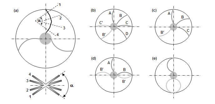
Curved vane spider
The intense spike produced by a straight vane on the bright stars
and planets can be visually eliminated by curving the vanes. The
result is a curved vane spider. Diffraction effect of a
curved vane can be illustrated by breaking it into a number of
smaller, practically straight sections, with varying orientations
(FIG. 110a).
While the total amount of energy produced by a curved vane is
identical to that of a straight vane of equal length and thickness,
it is spread out wide, making it practically invisible (it still
lowers the contrast the same, on average).
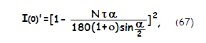
The peak diffraction intensity degradation factor is somewhat
different from that for the straight vanes (Eq. 65):
with α=180/N
being the vane arch angle in degrees. However, the result is only
slightly lower for given count (N) and relative thickness
(τ) of the vanes,
reflecting the slightly greater curved vane length.
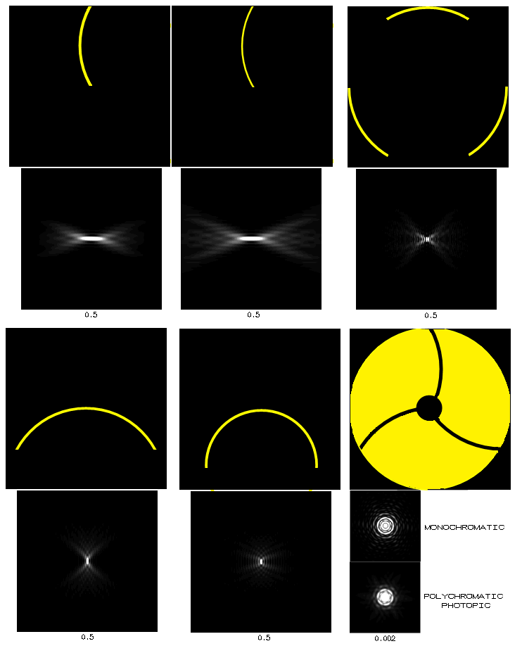
Using the same concept of inverse aperture, the actual energy
distribution of a curved vane can be simulated. It is shown, for
comparison, with those for the straight vane, and for a significantly
wider vane with one straight and one curved side (note that the
patterns are in their actual orientation vs. aperures-vanes). These
energy distribution patterns are deducted from the diffraction
distribution of the clear aperture, changing its appearance. The full
arc of the curved vane-aperture is 90 degrees, but the angle of energy
spread is only about 60 degrees, or little more. Three vanes of this
shape, properly positioned, would spread their energu in a nearly
continuous radial pattern, eliminating spikes (even a single curved
vane would probably make it invisible). This vane still produces an
elongated central maxima, but some 15 times shorter than a straight
vane of the same thickness, thus much less pronounced.
The middle vane shape illustrates that curving and "styling" the vane
shape has little influence on their diffraction effect; in general, the
inverse energy they are throwing onto the main diffraction pattern will
be determined by their relative size in its quantity, and by their
shape - approximately - in its shape. A vane like this (it would make
little difference if both sides were curved) would produce significantly
shorter spike than a thin straight vane, similar to the straight vane of
similar thickness. It is still well over twice longer than the curved
vane spike, and with much more energy - proportional to its area -
transferred out of the Airy disc. There is no shape that will magically
take vane diffraction away.
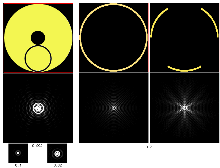
Following the same concept of inverse aperture, the pattern of energy
taken out by curved vanes can be also illustrated. For a single circular
vane, which seems to be the shape that nearly everything goes for,
simulation below shows no spike structure down to 0.002 intensity normalization,
i.e. where only portions with intensities below 1/500 the central intensity
show as shades of gray (left). Simulation next to it shows its pattern as
inverse aperture: most of the energy is concentrated in the small central maxima,
with the rest of it spreading out evenly, in concentric circles. On the
other hand, the 3-vane curved spider with 60-degree arcs creates uneven
energy spread, with a 6-fold spiky structure (not surprising looking at the
patern produced by a single 60-degree section). Those should be undetectable
most of the time, but could become visible on very bright objects. More
important, however, is that the total of energy transfered out of the
Airy disc is proportional to the vanes area, and the combined vane length of
the 3-vane spider is half the circumference of the circular shape they
belong to. Despite the vane apertures having proper orientation to cover
360° spread, this edge arrangement is not fully representative of
the actual vane arrangement, because the vane apertures are more widely
separated. Looking at a single 60° vane aperture at its actual position,
we see that the diffraction pattern is quite similar to that of the
alike edge aperture (below, top).
The spread widens as the vane gets thinner, with
the central maxima remaining unchanged. If the top aperture from the
triple 60° arrangement is removed (it is shown on the picture),
the pattern shows spiky structure, with only four spikes (top right).
A single curved vane belonging to a circle of the same diameter as the
aperture forms a 120° arc, hence it spread falls short of 360°
(bottom, left). For 360° it needs to be having a 180° arc, i.e.
to be belonging to a circle of
30% smaller diameter (bottom middle). Finally, diffraction pattern
of an actual 3-vane curved spider does show the presence of a 6-spike
structure, but significantly less pronounced (bottom right).
Unlike the whole aperture, where the Airy pattern is much more intense
than the vane energy, hence requiring very low normalization in order
to show its effects, vane aperture patterns have much lower central intensity
and show energy spread with even when normalized to their peak intensity. As a
reminder, the inverse apertures of central obstruction and spider vanes
take energy out of the principal diffraction
pattern, changing its relative intensity distribution; this means that
the bright areas are where most of the energy is
taken out. Depending on whether the matching areas of the principal pattern
are bright, or dark, the combined intensity will be lessened, or reinforced.
PSF of some other spider shapes are shown here.
|
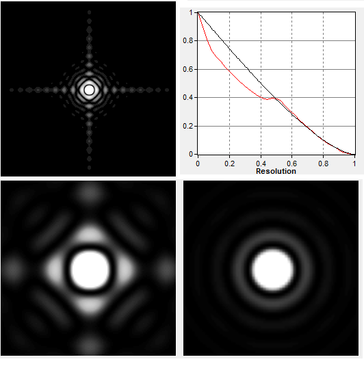 As with the CO effect, this diffraction peak degradation includes
the obscuration effect, which does not affect the relative energy
distribution within diffraction pattern. Factoring that in, the
relative degradation is given simply by (1-a). Another similarity
with the CO effect is that the 4-vane spider also makes
the central diffraction maxima smaller. However, while in
the case of CO it remains circular in shape, the 4-vane
spider makes it slightly rectangular, by slightly
flattening the central maxima on four sides where the
spikes come out. The reduction is roughly commensurate to
the area of obscuration, thus much smaller than with the
standard CO sizes. Simulation at left shows it for a
3-inch aperture and 4-vane spider with 5mm thick vanes
(no central obstruction), thus creating nearly 17%
obscuration - much more than the vanes usually do. The
MTF is also, for clarity, shown for this exaggerated
scenario. The contrast transfer improvement over the
perfect clear aperture is for the orientation shown; for
the pattern rotated by 45 degrees it would be smaller.
Compared to the CO effect, this contrast improvement in
this orientation drops off quickly after the initial gain
at mid frequencies, probably due to the vanes bringing
energy into the first dark ring. With the standard
thickness vanes, these effects are negligible, more so
considering that the actual vane area is reduced in the
presence of CO.
As with the CO effect, this diffraction peak degradation includes
the obscuration effect, which does not affect the relative energy
distribution within diffraction pattern. Factoring that in, the
relative degradation is given simply by (1-a). Another similarity
with the CO effect is that the 4-vane spider also makes
the central diffraction maxima smaller. However, while in
the case of CO it remains circular in shape, the 4-vane
spider makes it slightly rectangular, by slightly
flattening the central maxima on four sides where the
spikes come out. The reduction is roughly commensurate to
the area of obscuration, thus much smaller than with the
standard CO sizes. Simulation at left shows it for a
3-inch aperture and 4-vane spider with 5mm thick vanes
(no central obstruction), thus creating nearly 17%
obscuration - much more than the vanes usually do. The
MTF is also, for clarity, shown for this exaggerated
scenario. The contrast transfer improvement over the
perfect clear aperture is for the orientation shown; for
the pattern rotated by 45 degrees it would be smaller.
Compared to the CO effect, this contrast improvement in
this orientation drops off quickly after the initial gain
at mid frequencies, probably due to the vanes bringing
energy into the first dark ring. With the standard
thickness vanes, these effects are negligible, more so
considering that the actual vane area is reduced in the
presence of CO. 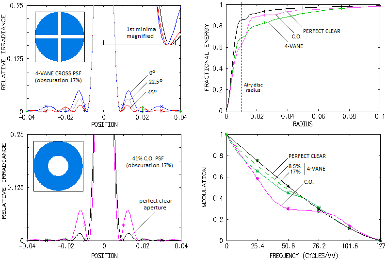 significantly less bright with the cross-like obscuration than
with with CO, with uneven intensity (given for three orientation,
zero degrees being along the horizontal, or vertical central line
of the PSF pattern), but with generally more energy in the outer
area. Encircled energy graphs top right show that this energy
beyond the 1st bright ring is significantly higher, despite the
cross-like obscuration encircling more energy in the central maxima
(approximately 80% of the energy content of Airy disc, vs. nearly
70% for the CO). The more energy beyond the 1st bright ring for
the cross-like obscuration is a consequence of roughly three times
more energy in the 1st bright ring with the CO. Taking that the
relative encircled energy in the central maxima is, as a quality
indicator, comparable to the Strehl, and for relatively small
disturbance levels nominally nearly identical, leads to the
conclusion that a 4-vane spider Strehl-like figure is somewhat
higher than for a CO of the same relative obscuration. In other
words, a standard 1-2% obscuration 4-vane spider would degrade the
effective Strehl by less than the corresponding 1-2% obscuration
CO, i.e. less than 10-14% linear CO.
significantly less bright with the cross-like obscuration than
with with CO, with uneven intensity (given for three orientation,
zero degrees being along the horizontal, or vertical central line
of the PSF pattern), but with generally more energy in the outer
area. Encircled energy graphs top right show that this energy
beyond the 1st bright ring is significantly higher, despite the
cross-like obscuration encircling more energy in the central maxima
(approximately 80% of the energy content of Airy disc, vs. nearly
70% for the CO). The more energy beyond the 1st bright ring for
the cross-like obscuration is a consequence of roughly three times
more energy in the 1st bright ring with the CO. Taking that the
relative encircled energy in the central maxima is, as a quality
indicator, comparable to the Strehl, and for relatively small
disturbance levels nominally nearly identical, leads to the
conclusion that a 4-vane spider Strehl-like figure is somewhat
higher than for a CO of the same relative obscuration. In other
words, a standard 1-2% obscuration 4-vane spider would degrade the
effective Strehl by less than the corresponding 1-2% obscuration
CO, i.e. less than 10-14% linear CO.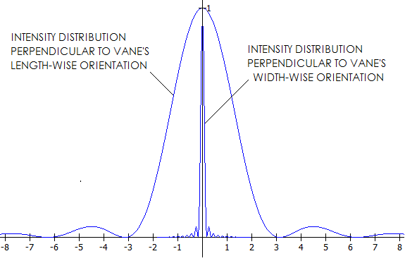 where x and y are the linear point
coordinates in image plane in the horizontal and vertical
direction, respectively. Evidently, this relation gives identical
distribution of minimas and maximas in the two perpendicular
planes as Eq. 66 (one perpendicular to the vane width, the
other to vane's height), with either x or y
being the equivalent of r under Eq. 66, and either
being zero along one of the two perpendicular axes in image plane.
Still, this relation is more complete since directly determining
intensity distribution along both perpendicular axes, and in any
chosen direction in the image plane.
where x and y are the linear point
coordinates in image plane in the horizontal and vertical
direction, respectively. Evidently, this relation gives identical
distribution of minimas and maximas in the two perpendicular
planes as Eq. 66 (one perpendicular to the vane width, the
other to vane's height), with either x or y
being the equivalent of r under Eq. 66, and either
being zero along one of the two perpendicular axes in image plane.
Still, this relation is more complete since directly determining
intensity distribution along both perpendicular axes, and in any
chosen direction in the image plane.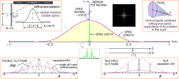 FIGURE 109: